PolyUMI (Part 2): Training and Deploying a Multimodal Manipulation Policy
This article is Part 2 of 2 on PolyUMI; Part 1 covers PolyUMI’s hardware, firmware, and data collection system. Here we cover the rest of the pipeline: preprocessing, dataset creation, training, and real-time policy deployment on a Franka FR3.
PolyUMI is a multimodal robot learning policy training, inference, and data collection platform, which enables rapid iteration on imitation learning policies beyond visuomotor.
The hardware platform includes a wireless UMI-style gripper with an optical tactile finger and a contact microphone (inspired by PolyTouch), plus a matching end-effector for a Franka arm. One button press records four synchronized streams — vision (GoPro), touch (finger camera), vibration (contact mic), and proprioception (SLAM/joint encoders+FK) — with no external PC required at collection time.
The training and inference platform is built from bottom-up as a distributed system using ROS2, docker, and zmq, to support drop-in substitution of new models into the inference pipeline (just rebuild the training/inference docker container, and point its API server to your new model), and separation of concerns between machine learning and robot control for better performance. The system’s ease-of-use has been proven in practice through a remote collaboration with Pearl Lab (TU Darmstadt), in which we have trained and deployed models developed by them with only ~30 minutes of sit-down work.
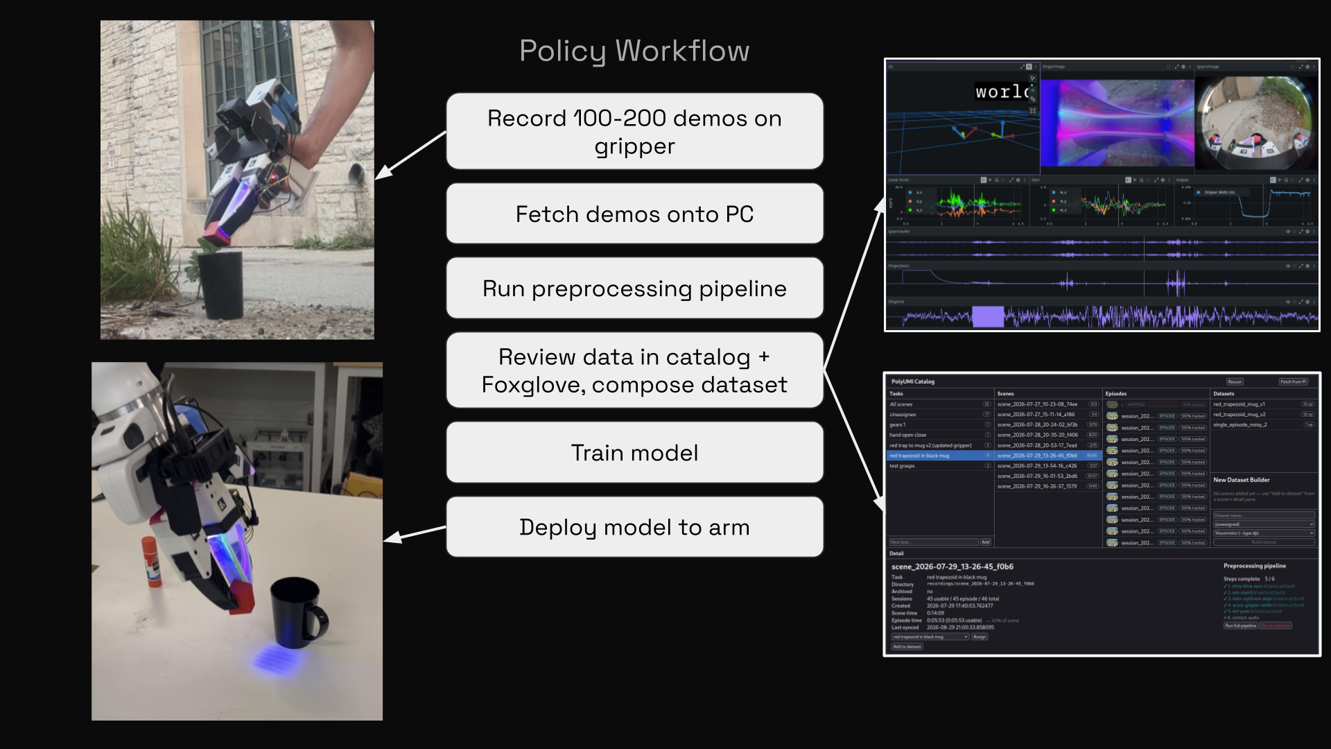
Data Pipeline: From Episode Recording to Training-Ready Dataset
Working Data Format
Recorded sessions are fetched and processed by pingest, PolyUMI’s preprocessing CLI, into a zarr-based working format (pzarr). It is deliberately not a training format, but instead a lossless, incrementally-writable store which is mutated in place by each preprocessing pipeline step.
- No resampling at storage time; every stream keeps its own native-rate timestamps.
- Lossless data storage for maximum flexibility and fast runtime.
- Steps are tracked per scene and are independently re-runnable, for ease of re-processing and development.
Training and visualization formats – e.g. diffusion_policy-style ReplayBuffer subclasses, MCAP, and potentially others – are lossy downstream artifacts of pzarr, and can be generated by pingest once preprocessing is complete.
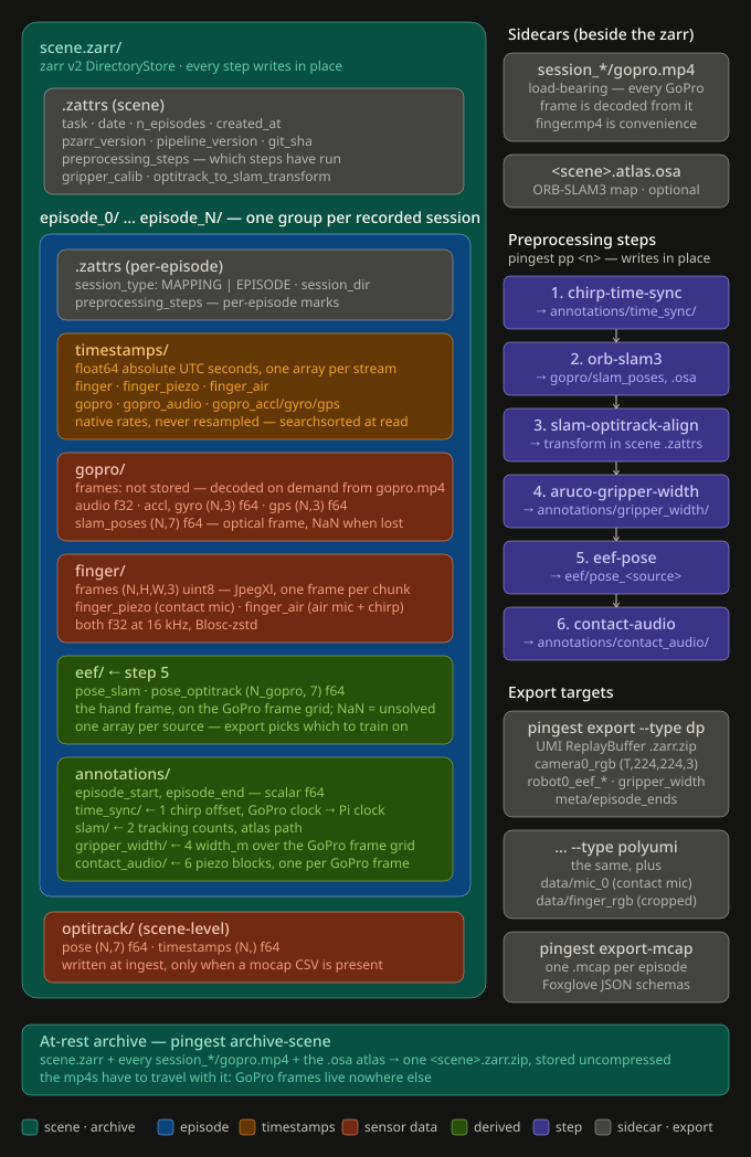
pzarr schema: one store per scene, one subgroup per episode, per-stream timestamps at native rates, and pipeline steps writing annotations in place. Sidecars (raw MP4s, SLAM atlas) sit alongside rather than inside. (click for full size)Pre-processing Pipeline
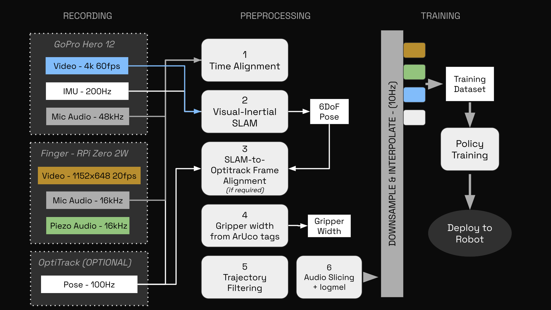
1. Chirp-based time alignment
The finger camera and mic run on the Pi’s clock, the GoPro on its own. At the start of each recording the Pi emits a linear frequency sweep from a piezo buzzer, captured by both the finger’s air mic and the GoPro’s mic. A matched filter recovers the chirp onset in both tracks; their difference is the offset between the two clock domains. No hardware sync line is required.
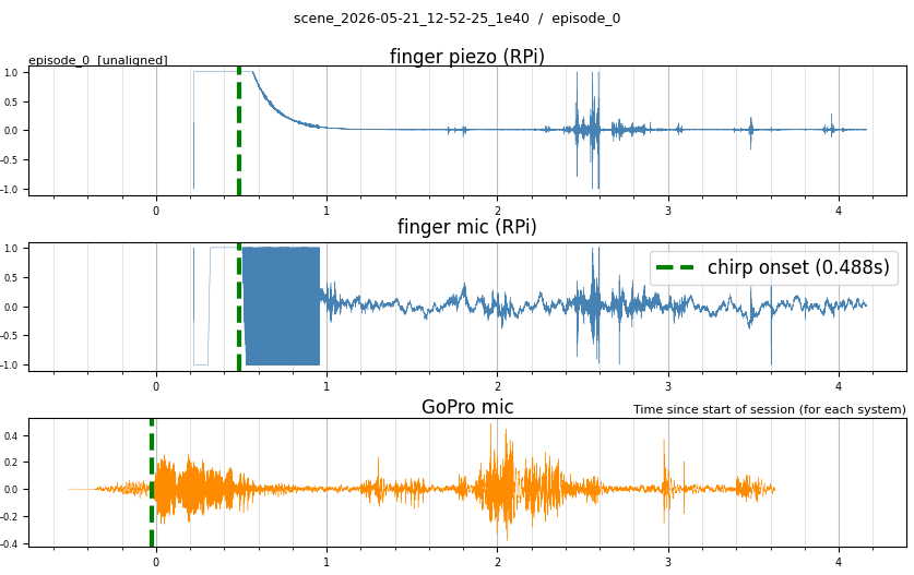
2. Visual-inertial SLAM
Following UMI, GoPro video and IMU are run through monocular-inertial SLAM (using PolyUMI’s fork of ORB-SLAM3) to recover a 6-DoF gripper trajectory.
The fork contains several notable changes relative to UMI’s fork for improved performance:
- Camera model and calibration. New settings for the GoPro Hero 12 + Max Lens Mod 2.0, calibrated with OpenImuCameraCalibrator; UMI’s fork targets a Hero 9.
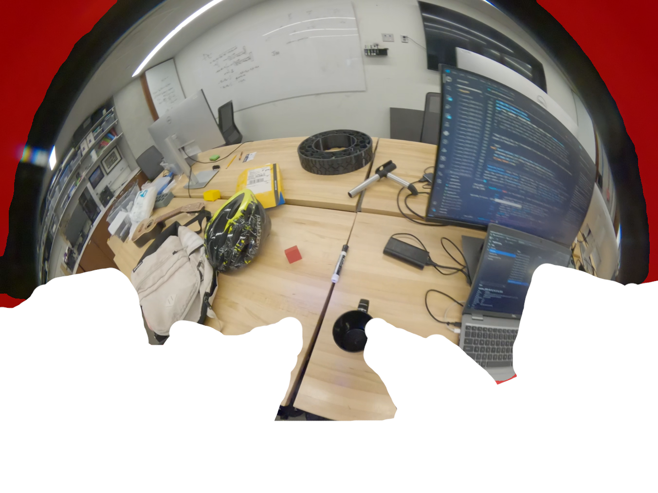
- Improved masking of the gripper hardware. The bottom ~35% of the GoPro’s view is the gripper itself. ORB-SLAM doesn’t intrinsically know this, and will waste ORB features on the gripper (which provide zero parallax). We mask out the gripper at the pixel level using a PNG mask (see below) to exactly remove the hardware from the view. Unmasked on one sample scene: 498 of 506 two-view reconstructions failed while mapping, and 39 of 62 episodes fail to localize; after masking, 59 of 62 localized.
- Corrected
is_loston poseless rows.Track()’s final branch fires both when tracking is lost and when the frame simply never got a pose — typically the frame right after initialization or relocalization — and in both cases republishes the previous frame’s pose and timestamp. It was recording those rows as tracked, so a duplicated pose at a repeated timestamp claimed to be real. All five consumers already read the flag as “this row has no pose of its own”, soUpdateFrameIMUhad been rescaling duplicated poses as if they were measurements. - Streaming decode and optional frame decimation. The frame buffer was being filled even on the single-pass path the pipeline actually runs, costing ~0.8 GB on short episodes and ~7 GB for a minute of video at ~4.1 MB per decoded frame. Single-pass now streams with one frame in flight. A
POLYUMI_SLAM_FRAME_STRIDEenv var adds optional temporal decimation to both binaries, bit-identical to previous behaviour when unset. - Robustness against the video decoder.
CAP_PROP_POS_MSECis unreliable on the last decoded frame under this OpenCV/FFmpeg build, occasionally reporting zero or a non-increasing value; timestamps are repaired to strictly increasing by extrapolated spacing.CAP_PROP_FPSreporting 0 or NaN was separately turning the mapper’s loop pacing intoinf, hanging the run. - ORB features raised to 2500, and more diagnostic output on tracking failure.
As well as some important changes relative to the original ORB-SLAM shared with UMI:
- Split into a mapper and a localizer. Two binaries: one builds a scene atlas, the other localizes against that prebuilt atlas. In pre-processing we perform one long mapping pass, then every demonstration episode is localized against that same map to ensure consistency (and save on runtime).
3. SLAM-to-OptiTrack alignment
PolyUMI supports capturing pose data from an OptiTrack motion capture system. This functionality was added primarily to evaluate SLAM performance, but can also be configured to replace SLAM as the pose trajectory source in training datasets.
To enable direct comparison of the SLAM and OptiTrack trajectories (if both are available), an SE(3) transform between the two frames is derived using Horn’s method as follows:
Given corresponding SLAM/OptiTrack positions \(\{p_i, q_i\}_{i=1}^N\) with centroids \(\bar p, \bar q\) and cross-covariance \(H = \sum_i (p_i-\bar p)(q_i-\bar q)^\top = U\Sigma V^\top\), the rotation and translation minimizing \(\sum_i \|Rp_i + t - q_i\|^2\) are given in closed form by
\[R = V\,\mathrm{diag}(1,\,1,\,\det(VU^\top))\,U^\top, \qquad t = \bar q - R\bar p,\]with the \(\det(VU^\top)\) term correcting for reflections so that \(\det R = +1\).
4. ArUco gripper width
Fiducials on the fingers are detected in the GoPro footage and solved via fisheye-undistorted PnP to give a per-frame width signal. This step follows UMI exactly.
5. Canonical end-effector pose
SLAM reports the GoPro’s optical frame; OptiTrack reports a marker rigid-body frame. Neither is a frame a policy can train on. Policies train on poses relative to the episode’s first, \(T_0^{-1}T_k\), from which a shared world frame cancels — but a body-frame offset \(X\) does not:
\[\left(T_0 X\right)^{-1}\left(T_k X\right) = X^{-1}\left(T_0^{-1} T_k\right) X\]leaving a \((R - I)x\) term in the relative translation: roughly 4 cm of phantom motion for a 30° wrist rotation at the 7 cm GoPro-to-fingertip scale. Both sources are therefore re-expressed onto the fingertip midpoint via the GoPro, which is the only body the handheld gripper and the arm-mounted end-effector share.
6. Contact-mic audio blocking
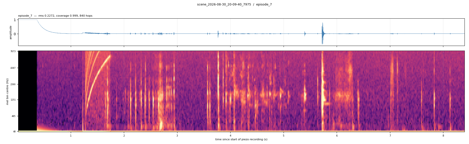
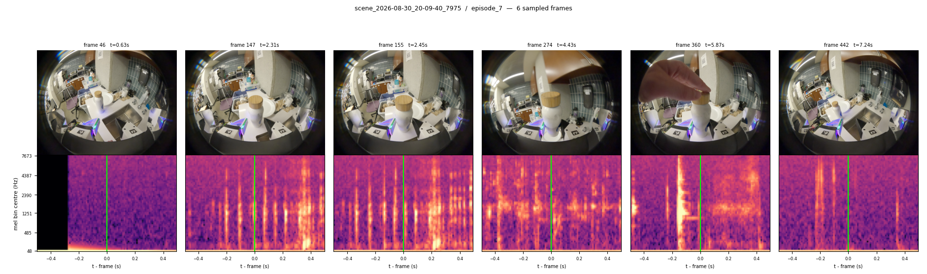
The 16 kHz piezo signal is sliced into one block per GoPro frame, anchored on each frame’s timestamp. This enables sending the audio in the form of log-mel spectrogram images into the downstream model, so that it can be consumed using a vision transformer (i.e. the pretrained AST ViT).
Data organization
A local web UI (polyumi-catalog) indexes the recordings directory into SQLite and browses tasks, scenes, sessions, and exported datasets. It also fetches from the Pi, re-runs pipeline steps, and opens episodes in Foxglove. It is a thin layer over the pipeline scripts rather than part of them.
Episodes replay into Foxglove through an MCAP export, and the end-effector streams live into the same layout during inference.
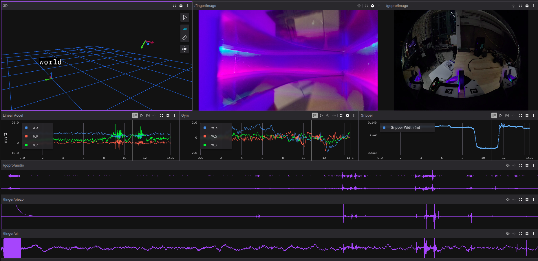
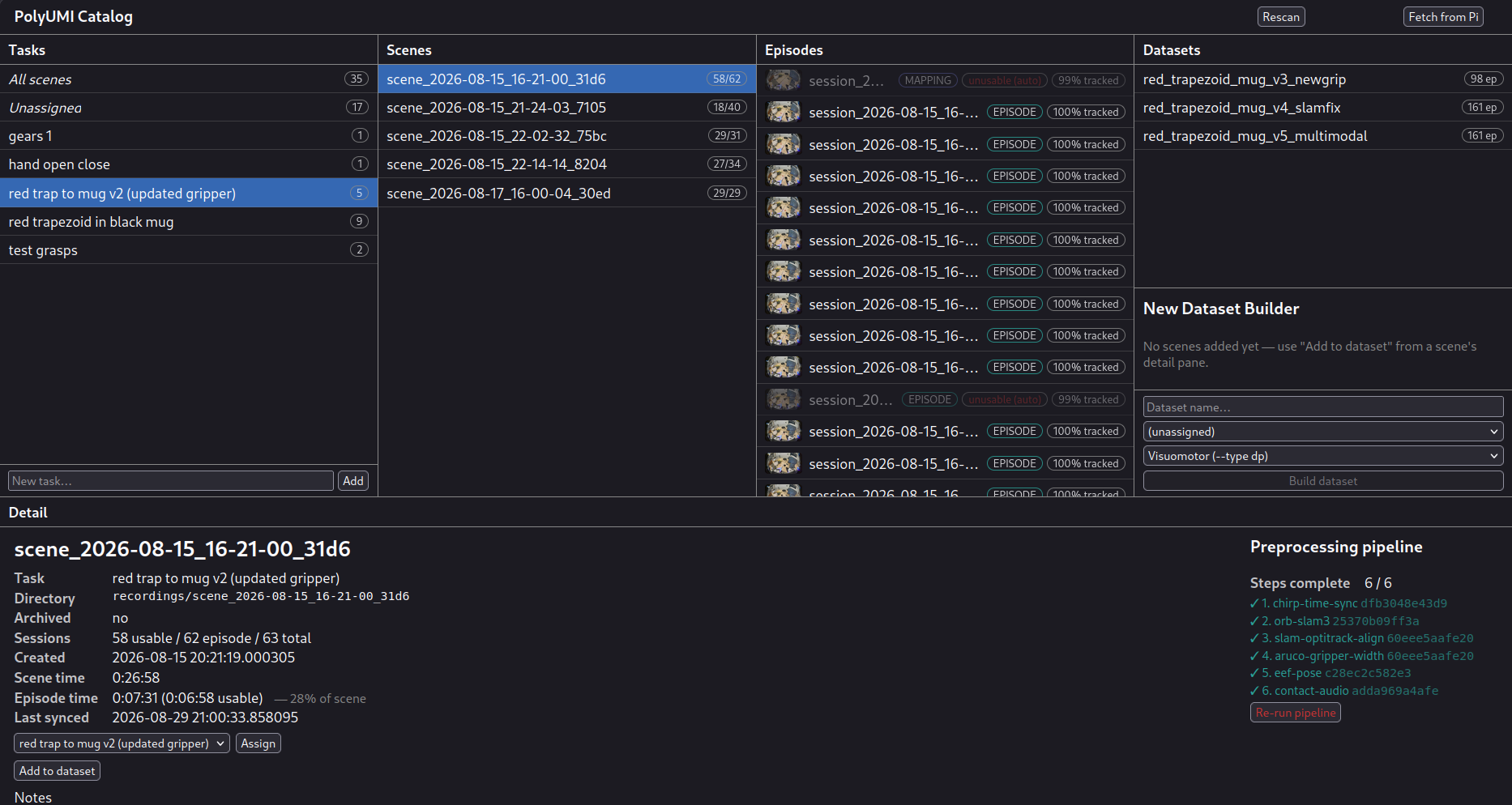
Right: Catalog UI showing detail on a scene.
Model Training
pingest export produces a UMI-compatible ReplayBuffer (.zarr.zip) that the training code reads directly. Training runs in Docker, since the training fork (built on UMI’s diffusion policy codebase) needs a conda/CUDA environment that conflicts with a host ROS install. The same image serves both training and inference: checkpoints are dill-pickled and unpickle only against the dependency tree they were trained under. The image builds in two cached stages — the base UMI environment, then the shared inference-protocol library — so editing the wire protocol does not rebuild the conda environment.
The first policy brought up end-to-end was visuomotor (vision and proprioception only), to validate the path from data through training and serving to the arm. The multimodal policy adding touch and audio is in development with a collaborator working on the model architecture; because the inference protocol is a separate library from the training code, integrating a model revision is a checkpoint swap rather than a system change.
Adding the contact mic and finger camera as observations follows ManiWAV, with three deltas:
- The export stores raw waveform, not a precomputed spectrogram. Mel parameters stay hyperparameters, and ManiWAV’s waveform-domain augmentations (background and robot-motor noise) remain possible.
- Audio blocks are causal — the frames ending at the observation instant. ManiWAV’s forward convention would supply 33 ms of audio at our step rate that does not exist yet at inference.
- The finger camera has no ManiWAV counterpart. It exports at native crop resolution, leaving the encoder input size to the training config.
Neither modality is consumed by a policy yet; the data contract and exporter are complete, the architecture and training recipe are current work.
PLACEHOLDER — figure/screenshot: training loss curves (visuomotor baseline) from Weights & Biases.
PLACEHOLDER — diagram: model architecture — proprioception through an MLP, vision/touch/audio through pretrained ViT encoders (timm/AST), pooled and projected into a diffusion policy head predicting SE(3) EE pose + gripper width. (The ICRA poster figure covers this, if usable directly.)
Model Deployment
Inference system overview
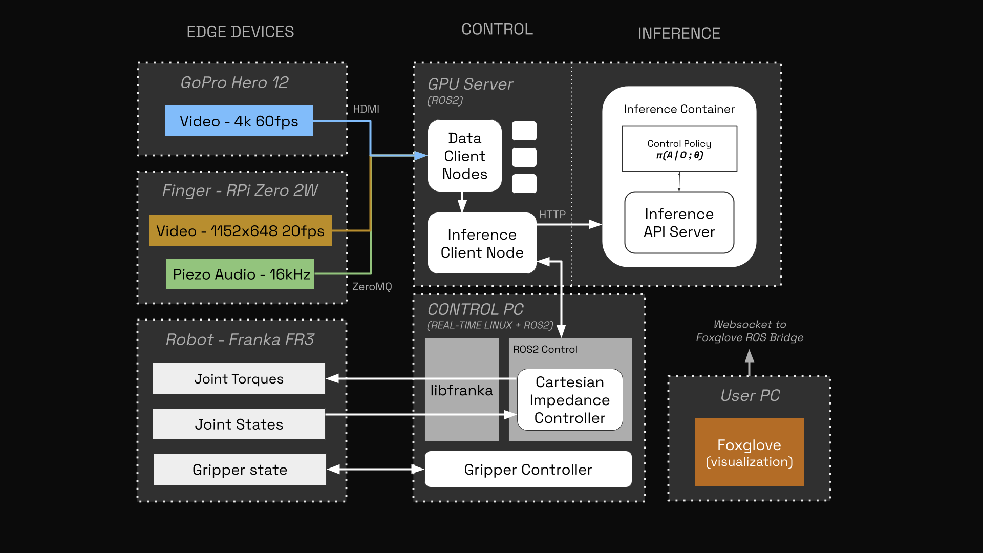
Due to the modular software architecture (ROS2 nodes for control, docker container for model), pieces of the above diagram can be moved to different compute units, but we run as follows for performance.
- A NUC running RT Linux (Ubuntu), which owns the Franka control stack (
ros2_control, the libfranka hardware interface) and runs the 1 kHz Cartesian impedance controller. - A GPU workstation, which runs the policy container and also runs the ROS2 client nodes. This minimizes network latency between model & ROS.
- The Raspberry Pi Zero 2W mounted on the gripper publishes tactile & audio data to the GPU workstation’s sensor client node over zmq (but does not run ROS itself due to resource constraints)
- A GoPro is routed through an ELGATO HDMI Capture Card, then into ROS2 through v4l2 for live video streaming.
- A laptop: only for visualization! Reads from Foxglove Bridge over websocket, so it doesn’t need ROS and is not on the data path between sensors, model, and arm.
All machines (except the laptop) are synchronized using NTP with chrony.
The three machines communicate over ROS 2, bridging a Kilted/Humble version gap through CycloneDDS on a dedicated link with unicast discovery. Each machine — including the gripper’s Pi — stamps data on its own clock, and drift between them corrupts every derived latency silently and pushes NUC-stamped TF outside the laptop’s buffer (“extrapolation into the past”). chrony on each machine, synced hierarchically to one reference host rather than to a public pool, holds them to sub-millisecond agreement.
The arm’s gripper is a Franka Hand modified for low latency & continuous position control, affectionately referred to as the FrankenHand (see repo maintained by Northwestern CRB here).
PLACEHOLDER — diagram: network and timing architecture across the four machines (Pi, laptop, NUC, GPU workstation), annotated with the chrony hierarchy and CycloneDDS domain boundaries.
Control: the Cartesian impedance controller
PolyUMI follows the two-layer hierarchy standard for this setting: the policy emits an action chunk of absolutely-timed end-effector waypoints at roughly 10 Hz, and a real-time controller tracks it at 1 kHz. The controller is a port of SERL’s Franka impedance controller (paper), itself derived from franka_ros’s reference implementation, and closely related to the law polymetis runs for UMI.
Given measured joint state \((q, \dot{q})\), the base-frame Jacobian \(J \in \mathbb{R}^{6\times7}\), and a reference pose from the interpolator, the pose error \(e \in \mathbb{R}^6\) stacks the translation error with the vector part of the difference quaternion, hemisphere-corrected and rotated into the base frame. The commanded torque is
\[\tau = J^\top\left(-K\bar{e} - D\,J\dot{q} - K_i e_I\right) + \left(I_7 - J^\top \left(J^\top\right)^{+}_{\lambda}\right)\left[K_n\left(q_n - q\right) - 2\sqrt{K_n}\,\dot{q}\right]\]where \(\bar{e}\) is the per-axis clipped error and the second term resolves the arm’s redundant seventh DOF through a damped pseudo-inverse (\(\lambda = 0.2\)). Joint 1 takes a stiffer nullspace tier (100 against 0.2) so base rotation is pinned while the elbow floats; \(K_i\) is zero in our configuration. The result is rate-limited against the previous commanded torque at 1 Nm per cycle, which libfranka requires.
| Parameter | Value | |
|---|---|---|
| \(K_{\mathrm{trans}}\) / \(D_{\mathrm{trans}}\) | 2000 N/m / 89 Ns/m | \(D \approx 2\sqrt{K}\), critically damped |
| \(K_{\mathrm{rot}}\) / \(D_{\mathrm{rot}}\) | 150 Nm/rad / 7 Nms/rad | under-damped, as in SERL and UMI |
| \(c_{\mathrm{trans}}\) / \(c_{\mathrm{rot}}\) | 0.01 m / 0.05 rad | error clip |
| \(K_n\) / \(K_{n,1}\) | 0.2 / 100 | nullspace |
Bounding interaction force is essential for contact-rich tasks, but lowering stiffness to achieve it costs tracking accuracy in free space. Following SERL, the error is instead clipped at the real-time layer, which caps commanded force at \(K_{\mathrm{trans}} c_{\mathrm{trans}} = 20\) N regardless of how far the reference has run from the measured pose — a stalled chunk and a policy commanding a pose inside the table produce the same bounded push. UMI’s spring is softer (750 N/m) but unbounded. \(c_{\mathrm{trans}}\) is therefore the single knob for contact force, and the FR3’s collision-reflex thresholds, which fire on estimated external force, must be raised alongside it.
The interpolator is a C++ port of UMI’s PoseTrajectoryInterpolator: piecewise-linear in position, slerp in orientation, over absolutely-timed waypoints. Its essential function is splicing — merging an arriving chunk into a trajectory already being consumed, without discontinuity at the current instant — which is what allows 10 Hz chunks to drive a loop that never stops between them. Waypoint speed is capped at 1.0 m/s and \(\pi\) rad/s, stretching a segment rather than letting the reference outrun the arm, since that lead distance sets contact force alongside the clip.
Finally, the policy’s body frame is the fingertip midpoint, while the arm reports its Jacobian roughly 15 cm away at the hand frame. A spring anchored at the wrong point converts orientation error into fingertip translation, so the Jacobian is shifted onto the TCP column-wise, \(J_{v,i} \leftarrow J_{v,i} + J_{\omega,i} \times r\), with the angular rows unchanged.
PLACEHOLDER — diagram: control block diagram — action chunk → interpolator (with speed clamps) → pose error → clip → impedance law + nullspace projection → torque-rate saturation → FCI, with the 10 Hz / 1 kHz rate boundary marked.
Latency and synchronization
In training data, every observation in a sample comes from the same GoPro frame grid. On the robot nothing is naturally synchronized, so live streams are aligned to the oldest measurement in the set. The pipeline is structured to support multi-rate streaming instead, for slow-fast architectures that do not sample every modality onto a common tick.
Latencies fall into three classes:
photon ──(latency.gopro)──> header.stamp ──(measured live)──> response ──(latency.arm_exec)──> motion
        CALIBRATE                          nothing to do                 CALIBRATE
header.stamp is the earliest instant the client can observe. Everything after it — color conversion, tick phasing, the POST, the network, the forward pass — is measured on every tick and converted directly into a count of leading actions to discard. Everything before it is calibrated offline: camera latency by filming a QR-encoded clock and differencing against the frame’s stamp (UMI measures 0.125–0.17 s on the same GoPro-to-capture-card chain), arm execution latency by chirping the commanded pose and cross-correlating against where the TCP actually went. Proprioception latency is adopted rather than measured, at ~1 ms; isolating it would need external ground truth of the true pose, and UMI hardcodes the same constant for the same reason.
The arm figure below is also the clearest measurement of what replacing MoveIt with the streaming impedance servo bought. Under MoveIt, the planner’s cadence capped how fast the arm could be swept, quantizing the measured trace and putting the correlation peak at 498 ms; against the servo the same probe returns 77 ms with a much sharper peak. A result still in the hundreds of milliseconds is the signature of something routing through the planner.
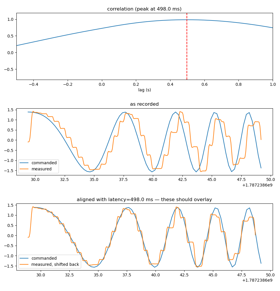
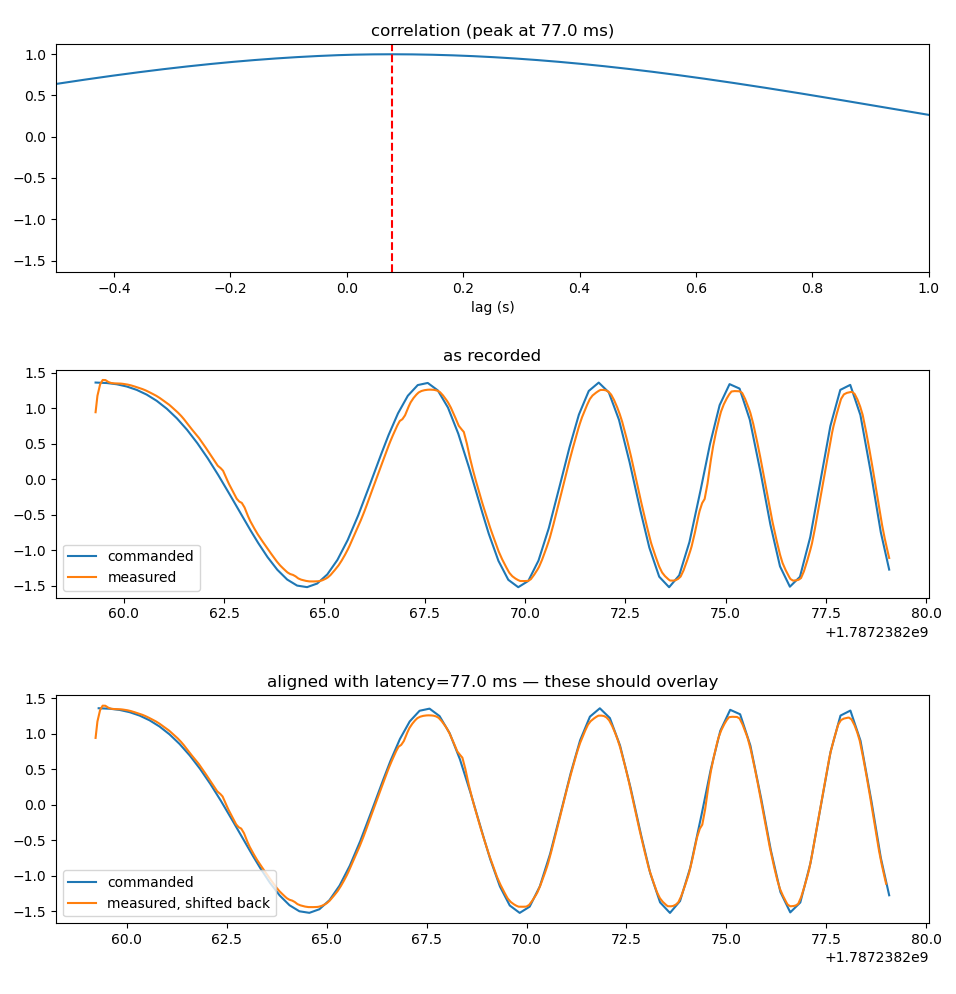
Latency at inference time forces the model to predict further out into the future, since we handle the latency by skipping the first n steps from the action chunk s.t. n/step_freq_hz == T_latency.
The binding constraint is that the chunk must outlast the latency budget:
\[t_{\mathrm{obs\ age}} + t_{\mathrm{exec}} < n_{\mathrm{action\ steps}} \cdot \Delta t_{\mathrm{action}}\]If it does not hold, every action has already elapsed on arrival and the arm does not move at all, while every other indicator reads healthy.
PLACEHOLDER — diagram: end-to-end latency diagram, photon to motion, with each calibrated/measured/adopted segment labeled.
PLACEHOLDER — screenshot: Foxglove latency-monitor plot during a live rollout.
Evaluation
Evaluation is in progress and is the subject of an upcoming publication. Planned ablations target which modalities contribute under which conditions — in particular whether the contact mic supplies only a binary contact signal or also discriminates materials and state changes. The evaluation tasks are chosen to stress what camera-only imitation struggles with: contact-rich dexterous tasks (pipetting, threading a lid), dynamic tasks infeasible to teleoperate (tossing an object into a bin), and conditions that degrade one modality, such as lighting changes during a rollout.
PLACEHOLDER: evaluation results — success rates per task and per ablation.
Lessons Learned
Lessons learned from bringing up a UMI system (no particular order):
- Latency is perhaps the hardest problem to solve at inference. the lower the total latency, the less the model has to predict the future. difficulty scales with:
- number of modalities (i have 4)
- number of compute nodes (at inference, I have 4, simplified down from 3. At data collection time, I have 4)
- nondeterminism (use wired connections where possible, etc)
- Measure what you can at runtime
- Calibrate out what you can’t using offline testing procedures
- Try to reduce mean + stdev as much as possible
- Control architecture is the unpublished “secret sauce”
- Arm:
- well-tuned, fast cartesian impedance controller for soft handling
- needs trajectory interpolation (+ smoothing for jittery policy outputs?)
- Gripper:
- real-time control required (note on Franka Hand)
- Arm:
- Naive data collection is an ideal, not a reality
- There are tricks to collecting good UMI policies – fully non-expert operators + fully embodiment-agnostic data collection isn’t realistic (at this data scale + system performance)
- Embodiment specific needs:
- Collect trajectories that respect the kinematics of the arm (ie workspace limits, don’t bottom out onto table, avoid joint singularities)
- Need to move deliberately enough so that your policy’s control frequency can capture the important moments for your task – especially contact rich ones. Unlike teleop, a umi policy can collect really fast trajectories and deploy them onto the arm–this doesn’t mean that you should do this, because these often perform worse
- Good SLAM performance is essential & tricky (even with my SLAM improvements) – you get the hang of it, but it takes trial and error
- Embodiment specific needs:
- Limiting the operator’s haptic & sensory feedback to what the gripper can record (even if just in imagination) is very helpful. Think through how the signals you have can help the model understand your task, and perform the task accordingly
- Still much more expressive than teleop!
- Stuff that gives you more expressiveness (given a policy & a set of modalities)
- Improved hardware performance (mechanism design)
- High system performance (low latency, high fidelity)
- Stuff that gives you more expressiveness (given a policy & a set of modalities)
- There are tricks to collecting good UMI policies – fully non-expert operators + fully embodiment-agnostic data collection isn’t realistic (at this data scale + system performance)
- Need to think through how to decrease domain gap between gripper & end-effector from day one in design phase. Need to iterate full-stack to improve this
- Examples:
- Audio noise improvement – embedded mic, gear tolerance tightening (show difference)
- Side window vs no side window
- Sensing surface improvement
- Examples:
- Data organization & visualization is key (ie catalog ui, foxglove, jupyter notebooks, etc)
- You will need a way to prune out bad episodes from your dataset etc
- Make data collection easy (good gripper design) pays dividends in policy & task development + performance (due to more expressive behavior capture). In-the-wild data, etc
- Need to have an intuitive understanding of the system’s performance, beyond just abstract. Your intuition is most powerful instrument for debugging, need to supply it with data. LLM’s are incredible at symbolic reasoning and can help you with bugs of that nature; but they usually can’t do this system-level thinking and physical intuition. Figure out a way to make your problems obvious visually, auditorially, use all your senses to understand the system and the problem.
Biggest takeaway:
- Getting a UMI-based imitation learning policy working requires a significant investment in systems & infrastructure, and each modality makes it harder. Don’t throw this away & don’t understimate the effort. Need to get the system performing really well in a good old fashioned engineering sense before model improvements even make a difference.
My timeline (roughly):
- 2months hardware + systems design & bringup (getting data signals in)
- 1 month firmware + data organization
- 2 months preprocessing
- 2 months inference system bringup (1 month of which is latency + control optimizations to get to first near task success)
- 1 month full-system iteration
Next Steps
- Publish paper in collaboration with TU Darmstadt.
Stuff I wish I could have done
- mirror curvature optimization
Citation
@inproceedings{hayes2026polyumi,
  title     = {PolyUMI: Visual + Auditory + Tactile Manipulation Platform for Imitation Learning},
  author    = {Hayes, Conor Wood},
  booktitle = {IEEE ICRA 2026 Workshop on Contact-Rich Robotic Manipulation (CR2)},
  year      = {2026},
  url       = {https://openreview.net/forum?id=Ou39QMiCMP}
}